Opel Corsa B 1993–2000 Service and Repair Manual: Cylinder head - overhaul
1. Unscrew the rocker arm retaining /adjustment nuts and withdraw the rocker arms from the studs. Keep them in order as they are removed.
2. To remove the valves, the springs will have to be compressed to allow the split collets to be released from the groove in the upper section of the valve stems. A valve spring compressor will therefore be necessary.
3. Locate the compressor to enable the forked end of the arm to be positioned over the valve spring collar whilst the screw part of the clamp is situated squarely on the face of the valve.
4. Screw up the clamp to compress the spring and release the pressure of the collar acting on the collets. If the collar sticks, support the head and clamp frame and give the end of the clamp a light tap with a hammer to help release it.
5. Extract the two collets and then release the tension of the clamp. Remove the clamp, withdraw the collar and spring and extract the valve. Remove the valve stem seals and the exhaust valve rotators.
6. As they are released and removed, keep the valves in order so that if they are to be refitted they will be replaced in their original positions in the cylinder head. A piece of stiff card with eight holes punched in it is a sure method of keeping the valves in order.
7. Examine the head of the valves for pitting and burning, especially the heads of the exhaust valves. The valve seating should be examined at the same time. If the pitting on valve and seat is very slight, the marks can be removed by grinding the seats and valves together with coarse, and then fine, valve grinding paste.
8. Where bad pitting has occurred to the valve seats it will be necessary to recut them and fit new valves. The latter job should be entrusted to the local agent or engineering works. In practice it is very seldom that the seats are so badly worn. Normally it is the valve that is too badly worn for refitting, and the owner can easily purchase a new set of valves and match them to the seats by valve grinding.
9. Valve grinding is carried out as follows.
Smear a trace of coarse carborundum paste on the seat face and apply a suction grinder tool to the valve head. With a semi-rotary motion, grind the valve head to its seat, lifting the valve occasionally to redistribute the grinding paste. When a dull matt even surface is produced on both the valve seat and the valve, wipe off the paste and repeat the process with fine carborundum paste, lifting and turning the valve to redistribute the paste as before. A light spring placed under the valve head will greatly ease this operation.
When a smooth unbroken ring of light grey matt finish is produced, on both valve and valve seat faces, the grinding operation is complete.
10. Scrape away all carbon from the valve head and the valve stem. Carefully clean away every trace of grinding compound; take great care to leave none in the ports or in the valve guides. Clean the valves and valve seats with a paraffin-soaked rag, then with a clean rag and finally, if an air line is available, blow the valves, valve guides and valve ports clean.
11. Check that all valve springs are intact. If any one is broken, all should be renewed.
Check the free height of the springs against new ones. If some springs are not within specification, replace them all. Springs suffer from fatigue and it is a good idea to renew them even if they look serviceable.
12. Check that the oil supply holes in the rocker arm studs are clear.
13. The cylinder head can be checked for warping either by placing it on a piece of plate glass or using a straight-edge and feeler blades. Slight distortion may be corrected by having the head machined to remove metal from the mating face.
14. Valve guide renewal is necessary if the valve stem clearance in the guide exceeds that specified. Renewal, or reaming to accept oversize valves, should be left to a GM dealer.
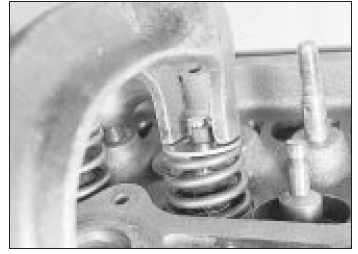
15. Commence reassembly by lubricating a valve stem and inserting it into its guide (see illustration).
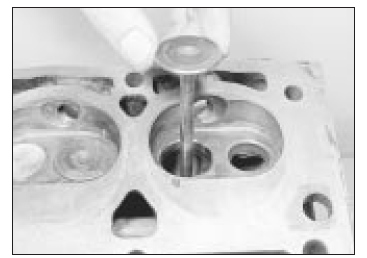
Fitting a valve to its guide
16. Fit the valve stem oil seal, using the protective sleeve supplied with the new seals over the valve stem to avoid damage.
Lubricate the sleeve and push on the seal, ring downwards. Recover the sleeve.
17. On exhaust valves, fit the valve rotator (see illustration).
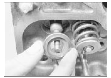
Fitting an exhaust valve rotator
18. Fit the valve spring and collar, with the recessed part of the collar inside the spring (see illustrations).
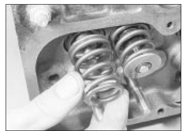
Fit the valve spring . . .
. . . followed by the spring collar
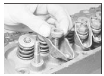
19. Place the end of the spring compressor over the collar and valve stem and, with the screw head of the compressor over the valve head, screw up the clamp until the spring is compressed past the groove in the valve stem. Then put a little grease round the groove.
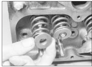
20. Place the two halves of the split collar (collets) into the groove with the narrow ends pointing towards the spring (see illustration).
The grease will hold them in the groove.
Compress the spring and fit the
collets
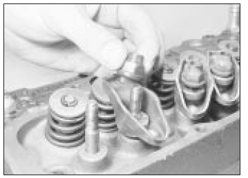
21. Release the clamp slowly and carefully, making sure that the collets are not dislodged from the groove. When the clamp is fully released the top edges of the collets should be in line with each other. Give the top of each spring a smart tap with a soft-faced mallet when assembly is complete to ensure that the collets are properly settled.
22. Repeat the above procedure for the other 7 valves.
23. The rocker gear can be refitted with the head either on or off the engine. The only part of the procedure to watch is that the rocker nuts must not be screwed down too far or it will not be possible to refit the pushrods.
24. Next put the rocker arm over the stud followed by the pivot ball (see illustrations).
Make sure that the spring fits snugly round the rocker arm centre section and that the two bearing surfaces of the interior of the arm and the ball face, are clean and lubricated with engine oil.

Fitting a rocker arm . . .
. . . and its pivot ball
25. Oil the stud thread and fit the nut with the self-locking collar uppermost (see illustration). Screw it down until the locking collar is on the stud.
Fit the nut with the self-locking collar
uppermost
 Cylinder head - removal and
refitting
Cylinder head - removal and
refitting
Removal
1. Make sure that the engine is cold before
commencing operations to avoid any chance
of the head distorting.
2. Disconnect the battery negative terminal
3. Drain the cooling system, an ...
 Cylinder head and pistons
- decarbonising
Cylinder head and pistons
- decarbonising
1. This can be carried out with the engine
either in or out of the car. With the cylinder
head removed, carefully use a wire brush and
blunt scraper to clean all traces of carbon
deposits from the ...
See also:
Opel Corsa B 1993–2000 Service and Repair Manual. Hose and fluid leak check
1. Visually inspect the engine joint faces,
gaskets and seals for any signs of water or oil
leaks. Pay particular attention to the areas
around the camshaft cover, cylinder head, oil
filter and su ...
