Opel Corsa B 1993–2000 Service and Repair Manual: Switches - removal and refitting
1. Before removing a switch, disconnect the battery negative lead.
Lighting master switch
2. Release the spring clips at the side of the switch by pressing them with a bent screwdriver or similar tool. Draw the switch out of the facia, disconnect its wiring plug and remove it (see illustration). If the switch cannot be released, remove the instrument panel surround.
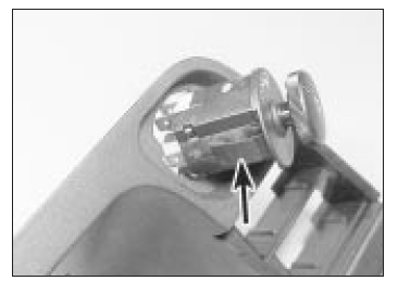
Removing the lighting master switch -
one of the spring clips is arrowed
3. To refit, connect the wiring plug to the switch and press the switch home until the clips snap into place.
Hazard warning switch
4. This is removed and refitted in the same way as the lighting master switch.
Foglamp switch
5. Carefully prise the switch from its location, disconnect its wires and withdraw it (see illustration).
6. Refit in the reverse order to removal.
Removing a foglamp switch
Instrument illumination control
7. Remove the instrument panel surround.
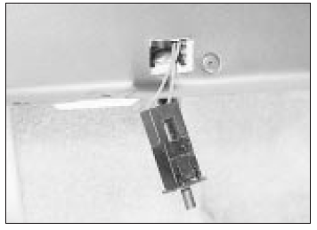
8. Slacken the securing screw and remove the illumination control (see illustration).
9. Refit in the reverse order to removal.
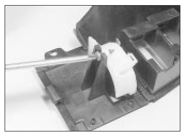
Removing the instrument illumination
control
Heater blower/heated rear window switch
10. This switch is released in a similar way to the lighting master switch. If the switch cannot be released, withdraw the heater control panel.
11. Refit in the reverse order to removal.
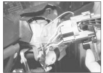
Steering column switches
12. Although not strictly necessary, access will be improved if the steering wheel is removed.
Otherwise, remove the wheel centre trim.
13. Remove the upper and lower switch shrouds. These are held in place by eight screws with the fixed type steering wheel, or five screws with the adjustable wheel.
14. In theory it is now possible to unclip and withdraw either of the multi-function switches.
In practice it was found necessary, when the adjustable wheel was fitted, to undo the two switch housing screws and draw the switch assembly up the column slightly. The switch in question can then be unplugged, unclipped and removed (see illustrations).
15. Refit in the reverse order to removal.
Drawing the steering column
switches up the column
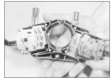
Unclipping a steering column switch
- assembly removed for clarity
Stop-lamp switch
16. Remove the stop-lamp switch by turning it 90º left or right and withdrawing it from its bracket.
17. Before fitting the stop-lamp switch, pull its plunger out as far as it will go. The switch will adjust itself once it is fitted.
Handbrake warning switch
18. Without disconnecting the handbrake lever from the yoke.
Electric mirror switch
19. Free the rear half of the centre console.
20. Disconnect and unclip the switch.
21. Refit in the reverse order to removal.
Electric window winder switch
22. Proceed as described above for the electric mirror switch.
Interior light switches
23. The main interior light is operated by door plunger switches. Similar switches control the luggage area and glovebox light, when fitted.
24. Removal is similar in every case. After displacing any trim which may be in the way, the switch is unscrewed or unclipped and withdrawn from its location (see illustrations). The electrical lead(s) can then be unplugged and the switch removed. Tape the wires if necessary to avoid losing them inside the switch hole.
Glovebox light switch unclipped from
its location
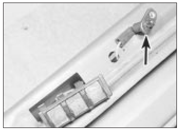
Luggage area light switch (arrowed) next to contact plate on tailgate
sill
25. Refit in the reverse order to removal.
Check for correct operation before refitting any trim.
Horn(s) - removal and refitting
Removal
1. The horn itself is located in front of the radiator, unless an oil cooler is fitted, when it is located behind the battery. Disconnect and unbolt the horn to remove it; remove the front trim panel if necessary for access.
2. On models with twin horns, the second horn is mounted behind the front grille on the left-hand side. To gain access to it, either the front grille or the radiator must be removed.
3. If the horn does not work, check with a 12 volt test lamp that voltage is present at the horn terminals when the horn push is operated. If the horn itself is defective it must be renewed.
Refitting
4. Refit in the reverse order to removal.
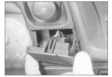
 Fuses and relays - general
information
Fuses and relays - general
information
1. All the car's electrical circuits are protected
by fuses; most of the fuses are found in a
fuse/relay box located under a cover to the
right of and below the steering column (see
illustration). ...
 Clock - removal and refitting
Removal
1. Disconnect the battery earth lead.
2. Carefully pull the clock from its location.
Disconnect the supply and illumination leads
from the clock and remove it (see
illustration).
R ...
See also:
Opel Corsa B 1993–2000 Service and Repair Manual. Spark plug renewal
1. The correct functioning of the spark plugs is
vital for the correct running and efficiency of
the engine. It is essential that the plugs fitted
are appropriate for the engine, the suitable
type ...
