Opel Corsa B 1993–2000 Service and Repair Manual: Idle speed and mixture adjustments
1. Before checking the idle speed and mixture setting, always check first the following.
- Check that the ignition timing is accurate.
- Check that the spark plugs are in good condition and correctly gapped.
- Check that the accelerator cable and, on carburettor models, the choke cable (where fitted) is correctly adjusted .
- Check that the crankcase breather hoses are secure with no leaks or kinks.
- Check that the air cleaner filter element is clean.
- Check that the exhaust system is in good condition .
- If the engine is running very roughly, check the compression pressures.
2. Take the car on a journey of sufficient length to warm it up to normal operating temperature. Proceed as described under the relevant sub-heading.
Note: Adjustment should be completed within two minutes of return, without stopping the engine. If this cannot be achieved, or if the radiator electric cooling fan operates, wait for the cooling fan to stop and clear any excess fuel from the inlet manifold by racing the engine two or three times to between 2000 and 3000 rpm, then allow it to idle again.
Carburettor models
3. Connect a tachometer in accordance with the manufacturer's instructions.
4. If the idle speed is outside the specified tolerance, turn the adjustment screw as necessary (see illustrations). This will not alter the CO content of the exhaust gas to any extent.
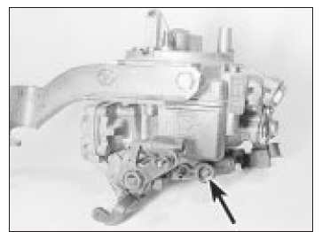
Idle speed adjustment screw
(arrowed) - 32TL carburettor
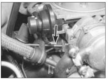
Idle speed adjustment screw
(arrowed) - 2E3 carburettor
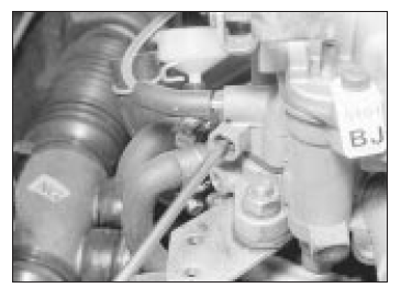
Adjusting the idle speed - Varajet
carburettor
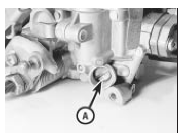
Idle speed adjusting screw (A) - 1B1
carburettor
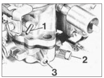
Idle adjustment points - 35PDSI
carburettor
- Distributor vacuum take-off
- Idle speed adjustment screw
- Mixture (CO level) adjustment screw
5. If an exhaust gas analyser is available, check the exhaust gas CO content as follows.
6. Remove the tamperproof cap (where fitted) from the mixture adjustment screw. Satisfy yourself that you are not breaking any local or national laws by so doing.
7. With the engine at normal operating temperature, check the CO content of the exhaust gas. If it is outside the permitted tolerance, turn the mixture adjusting screw as necessary to correct it (see illustrations).
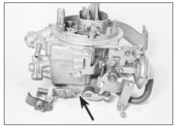
Mixture (CO) adjustment screw -
32TL carburettor
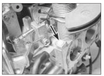
Mixture (CO) adjustment screw cap
(arrowed) 2E3 carburettor
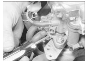
Adjusting the mixture (CO) setting -
Varajet carburettor
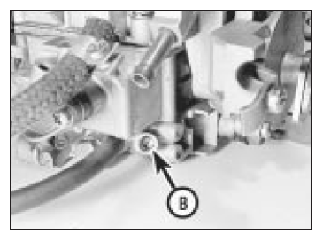
Mixture (CO) adjustment screw (B) -
1B1 carburettor
8. When the adjustments are correct, fit a new tamperproof cap to the screw and disconnect the tachometer.
Note: On 32TL and Varajet II carburettors, if it proves difficult to adjust the idle speed and/or mixture setting then it is likely that the base idle speed is incorrect.
Setting of this requires the use of an accurate vacuum gauge and should therefore be entrusted to a Vauxhall/Opel dealer.
Fuel-injected models
1.8 litre models
9. With the engine at normal operating temperature, connect a tachometer in accordance with its manufacturer's instructions.
10. Allow the engine to idle, and compare the idle speed with that given in the Specifications. If adjustment is necessary, slacken the locknut and turn the idle speed adjusting screw until the specified speed is obtained. The adjusting screw is situated on the throttle valve housing. Tighten the locknut on completion.
11. If an exhaust gas analyser is available, check the mixture (CO level) as follows.
12. With the engine idling at the specified speed, read the CO level and compare it with that specified.
13. If adjustment is necessary, remove the tamperproof cap from the mixture adjusting screw on the airflow sensor (see illustration).
Turn the screw clockwise to enrich the mixture, and anti-clockwise to weaken it.
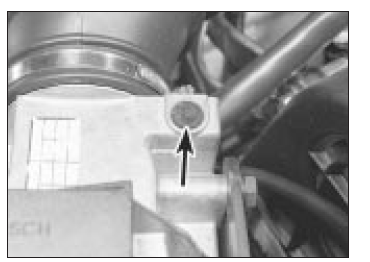
On 1.8 litre fuel-injected models the
mixture adjustment screw is located under
the cap on the airflow sensor
14. On completion, re-adjust the idle speed if necessary. Note that failure to bring the CO level within the specified range indicates a fault in the injection system, or a worn engine.
2.0 litre models
15. On all models the idle speed is automatically controlled by the electronic control unit and is not adjustable. If it is found to be incorrect then a fault is present in the fuel injection/ignition system.
16. On models without a catalytic converter, the mixture (CO level) can be adjusted as described above in paragraphs 9 and 11 to 14. On 16-valve models the adjusting screw is on the air mass meter (see illustration).
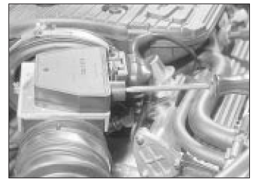
Adjusting the mixture (CO) setting -
2.0 litre 16-valve models
17. On models fitted with a catalytic converter, the mixture (CO level) is also automatically controlled by the electronic control unit and is not adjustable. If it is found to be incorrect then a fault is present in the fuel injection/ignition system.
1.4 and 1.6 litre models
18. On 1.4 and 1.6 litre models both the idle speed and mixture CO content are automatically controlled by the control unit and cannot be manually adjusted. If necessary, they can be checked by if they are found to be incorrect then a fault is present in the fuel injection/ignition system.
Fuel pump filter cleaning - carburettor models
Warning: Before carrying out the following operation refer to the precautions given in Safety first! and follow them implicitly.
Petrol is a highly dangerous and volatile liquid and the precautions necessary when handling it cannot be overstressed
Note: On some models the fuel pump may be a sealed unit, in which case this procedure is not necessary.
1. Place a wad of rag underneath the fuel pump to catch the fuel which will be spilt during the following operation.
2. Undo the retaining screw and remove the end cover from the fuel pump. Recover the rubber seal (see illustration).
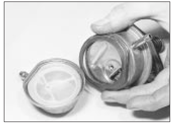
Removing the fuel pump cover, filter
and rubber seal - carburettor models
3. Remove the filter from the cover and wash it fresh fuel to remove any debris from it.
Inspect the filter for signs of clogging or splitting and renew it if necessary.
4. Locate the filter in the cover and fit the rubber seal.
5. Refit the cover to the pump and securely tighten its retaining screw.
6. Start the engine and check for signs of fuel leakage.
Automatic transmission fluid level check
1. To check the fluid level, the vehicle must be parked on level ground. Apply the handbrake.
2. If the transmission fluid is cold (ie, if the engine is cold), the level check must be completed with the engine idling, within one minute of the engine being started.
3. With the engine idling, fully depress the brake pedal, and move the gear selector lever smoothly through all positions, finishing in position "P".
4. With the engine still idling, withdraw the transmission fluid level dipstick (located at the left-hand side of the engine compartment, next to the engine oil level dipstick). Pull up the lever on the top of the dipstick to release it from the tube. Wipe the dipstick clean with a lint-free rag, re-insert it and withdraw it again.
5. If the transmission fluid was cold at the beginning of the procedure, the fluid level should be on the "MAX" mark on the side of the dipstick marked "+20ºC". Note that 0.4 litres of fluid is required to raise the level from the "MIN" to the "MAX" mark.
6. If the transmission fluid was at operating temperature at the beginning of the procedure (ie, if the vehicle had been driven for at least 12 miles/20 km), the fluid level should be between the "MIN" and "MAX" marks on the side of the dipstick marked "+94ºC". Note that 0.2 litres of fluid is required to raise the level from the "MIN" to the "MAX" mark.
7. If topping-up is necessary, stop the engine, and top-up with the specified type of fluid through the transmission dipstick tube.
8. Re-check the level, and refit the dipstick on completion.
Electrical system check
1. Check the operation of all the electrical equipment, ie lights, direction indicators, horn, etc.
2. Note that stop-light switch adjustment.
3. Check all accessible wiring connectors, harnesses and retaining clips for security, and for signs of chafing or damage. Rectify any faults found.
Wiper blade check
Check the condition of the wiper blades. If they are cracked, or show any signs of deterioration, or if they fail to clean the glass effectively, renew the blades. Ideally, the wiper blades should be renewed annually as a matter of course.
To remove a wiper blade, pull the arm away from the glass until it locks. Swivel the blade through 90º, then squeeze the locking clip, and detach the blade from the arm. When fitting the new blade, make sure that the blade locks securely into the arm, and that the blade is orientated correctly.
Roadwheel bolt tightness check
Using a torque wrench on each wheel bolt in turn, ensure that the bolts are tightened to the specified torque.
Brake pad, caliper and disc check
Front brakes
1. Apply the handbrake, then jack up the front of the vehicle and support securely on axle stands; remove the roadwheels.
2. For a quick check, the thickness of friction material remaining on each pad can be measured through the slot in the front of the caliper body (see illustration). If any pad is worn to the minimum thickness or less, all four pads must be renewed .
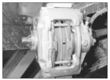
The thickness of the brake pads are
visible through the caliper aperture
3. For a complete check, the brake pads should be removed and cleaned. This will allow the operation of the caliper to be checked, and the condition of the brake disc itself to be fully examined on both sides.
Rear brakes
4. Chock the front wheels, then jack up the rear of the vehicle and support securely on axle stands; remove the roadwheels. Inspect the pads as described in paragraphs 2 and 3.
 Auxiliary drivebelt check and
renewal
Alternator drivebelt
Checking and adjustment
1. Correct tensioning of the auxiliary drivebelt
will ensure that it has a long life. Beware,
however, of overtightening, as this can cause
excessive ...
 Handbrake adjustment
Rear drum brake models
1. Normal adjustment of the handbrake takes
place automatically due to the self-adjusting
mechanism of the rear brakes. To
compensate for cable stretch, or after a new
cabl ...
See also:
Opel Corsa B 1993–2000 Service and Repair Manual. Oil pump - removal and
refitting
Removal
1. Remove the camshaft toothed belt and the sump.
2. Slacken and remove the crankshaft sprocket centre bolt and remove the
sprocket and spacers, noting their correct
fitted locations. Extr ...
